User Tools
Site Tools
Sidebar
Dinosaur
A tutorial by Thomas Roussel.
This tutorial shows an advanced Box Modeling creation. This technique has the advantage of quickly creating volumes and thus allows you to quickly visualize your work as it is modeled. This technique is especially well suited for beginners. We chose a dinosaur model because this kind of model is a bit complex while also being simple to create!
Furthermore, this model could be useful as a base for future displacement and painting sessions, and will be a perfect training model for learning these new features of Hexagon 2.
You may find it helpful before starting your creation to do some research to find photographs or drawings of dinosaurs to help you to better build your model!
Notes:
- Shortcuts are mentioned between parentheses, such as “Use Edge-tools (E) then…”.
- “E” is the shortcut for the “Edge-Tools”.
- All manipulations are based on the Universal Manipulator.
Tools Used
- Cube: The base primitive. This tool will be used only once.
- Fast Extrusion: A widely used tool. One of its advantages is to have a direct shortcut: the Ctrl key (or Command on Macintosh).
- Extrusion and Sweeping: These two tools let you extract polygons in more complex and advanced ways than the Fast Extrusion. For your information, these two tools are basically identical, except that the default tool option is not the same one.
- Tweak (Q): The ultimate model refinement tool. Do not forget to Validate the tool once your modifications are performed.
- Edge tools (E): This tool is in fact a set of three tools, providing you with a single access to perform several useful modifications on the models.
- Connect (X): This tool, associated with the Ring tool, lets you quickly perform various topology cuts.
- Tesselation (X): This tool lets you perform a continuous topology cut, or lets you cut polygons by slice. Note that its shortcut is the same as for the Connect tool. These two tools are in fact the same, but behave differently according to the active selection.
- Smoothing (PageUp / PageDown): This tool lets you smooth the object, by subdividing them.
- Symmetry Tool, with Clone option: This tool generates a mirror copy of the original model, according to a specified plane. The Clone option replicates all modifications on the second half of the model.
- Symmetry Mode: This is not a tool, but an object property. This property replicates all manipulations performed on one half of a symmetric model, to the mirror part.
- Loop (L), Ring (K) and Select Between (J): This tools work on selections. Keep in mind the shortcuts, because this set of features will be widely used in all modeling sessions.
Modeling Steps
The Pelvis Base, the Neck and the Head

This first step may seem to be the easiest one, but many things will be defined here. To start modeling your Dinosaur, you need a base. Start from a cube, which you will afterwards extrude and modify.
What you will wonder here is: will this cube be the head, a leg, or the end of the tail?
For this modeling tutorial, you will start from the pelvis, because this part is going to be the center of the model: the tail and the spine will be drawn from this center piece. Then the head, front legs and finally the back legs will be created.
This is not the only method that could be used, and it will be up to you to find the method you feel is best as you create more models and try new creations.
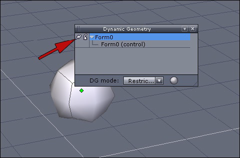
The starting cube lacks “resolution”, or polygons. Apply a first smoothing (PageUp).
The smoothing is a dynamic operation, but we want to “generate” this smoothed geometry and want to get the subdivided model as the basic one.
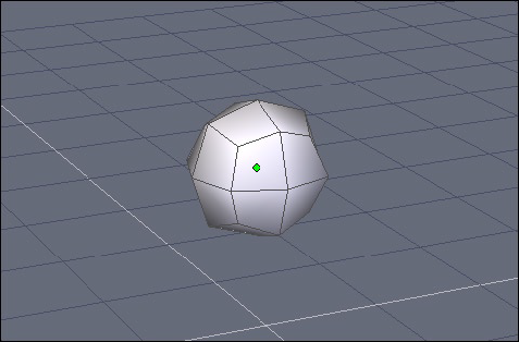
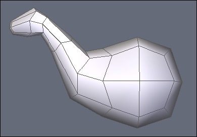
To convert this smoothing operation into static geometry, we have to “collapse” the Dynamic Geometry by clicking the small icon which looks like a lightning bolt, located in the top left corner of the Dynamic Geometry Panel. You should then see your smoothed cube being displayed as shown below:
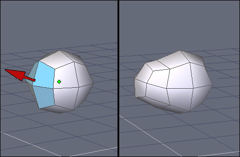
Select the four polygons as shown, which will let you extract geometry to start the spine. For this operation, the easiest way is to use the Fast Extrusion Tool (Ctrl) while clicking on the small yellow sphere. Once the extrusion is done, pull the extracted polygons upward.

Do the same operation again to extract the base of the neck (Select polygons, Fast Extrusion (Ctrl) and pull the selection upward with the Manipulator.
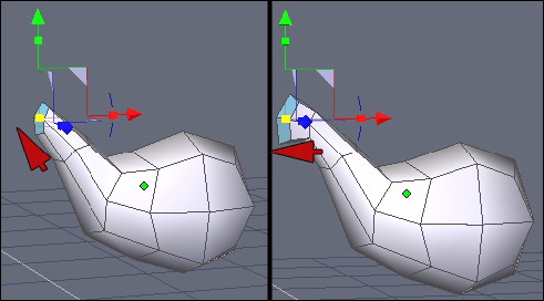
Do this operation sequence two more times to continue modeling the neck and to create the base of the head.
After a last extrusion, you will have the neck and the base which will be used for the head a bit later.
Symmetry, Tweaking and Tail Creation

For the following operations, it will be more convenient to activate the Symmetry Mode, located in the Property Panel, or in the Contextual Menu. Click on the “Symmetry” button. The right symmetry plane will be automatically detected.
The advantage of turning this mode on right now is simple: if you wish to tune the global aspect of your shape using the Tweak tool, the vertex or polygon displacements you will perform will be replicated on the other side and your model will stay symmetrical.
This mode will also replicate extrusion operations on the mirror half, such as for the extrusions we will perform to model the legs.
Take the opportunity now to extract the start of the Dinosaur’s tail, using the same method as used for the neck and the head modeling steps.
As shown on the shot above, do additional extrusions for the tail. To speed up the creation process, you can use the Sweeping tool to perform a sequence of Extrusions while staying in the same tool. Do not forget that the right click allows you to change the sweeping radius on the fly.
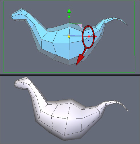
For the next steps of the modeling, it could be necessary to slightly modify the global orientation of the model. This is a small “trick”:
Instead of making a rotation in object mode, which will affect the bounding box of the object (and thus which could generate unwanted results afterwards), it is better to rotate the geometry itself: switch to Face Selection Mode, select all polygons, and perform a rotation as shown on the snapshot above. You can also try to do the rotation in Object Mode and in Face Mode to compare!
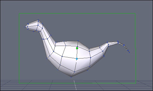
Before extracting polygons further, take the Tweak Tool, to refine a bit the shape of the model, and make the geometry a bit more “harmonious”.
Do not hesitate to compare with the previous snapshots. This step is more important than it seems, because if you do not make sure your proportions look nice on the basic model, further extracted parts will inherit the possible proportion problems.
Keep in mind that your model must be as accurate as possible at all steps of its construction.
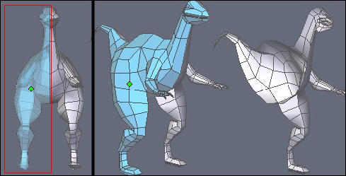
Building the Rear Legs
To extrude the legs, you must first prepare the part from where there are going to be extruded. Tweak if needed the polygons corresponding to the haunches (a bit to the rear, rounding them a bit).
From the selection, using the Fast Extrusion tool, extract a row of polygons. Modify them if necessary.
The legs will start from the bottom of this extrusion. Now will be the time to modify the polygons that will be the base of the extrusion.
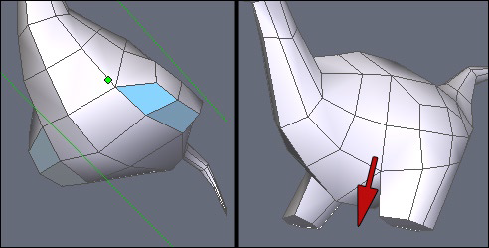
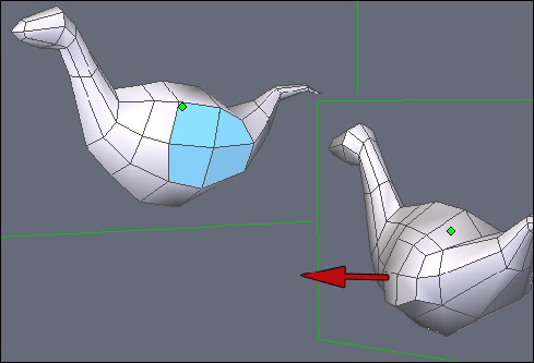
At left, polygons which are going to be extracted and to the right, the result of the extrusion, using the Fast Extrusion (Ctrl).
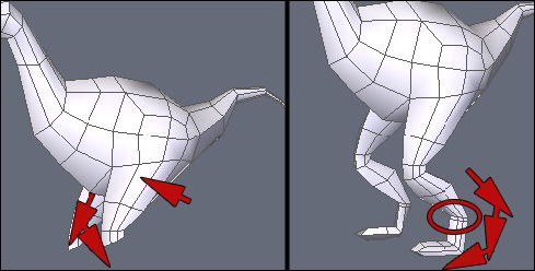
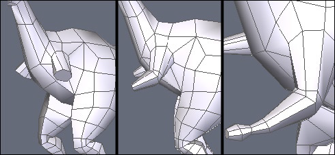
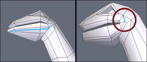
Continue to extract legs. After each extrusion, do not hesitate to modify the extracted polygons. As you can see on the left snapshot, the thigh is oriented toward the front, and a rotation at the knee level has been done.
At right, the end of the leg and the foot. Indicated by the red circle, a small extrusion is created. Consider doing the same with you work, as it will be important when we will smooth our model.
To finish the base of the legs, we have to modify a bit this base and start to add some cuts in order to get a model with a finer resolution.
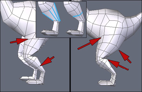
If you look closer at the snapshots of the previous step, the legs are rather straight. You have to add slices.
The fastest method is to do what we call a “Cut from Ring”. Do not look for this tool in Hexagon. It’s in fact a combination of the Ring Selection Tool (K), with the Connect Tool (X). Select an edge of the tibia, then do a Ring (K), then a Connect (X): a “slice” cut, or a cross-section, has been added, as shown in the small inset of the above picture.
Keep this combination in mind. It will be widely used again. A small tip: select an edge, then hit “K” and “X” to perform a “Cut from Ring”.
Do several cuts on the legs as shown on the left shot and then tweak this additional geometry, as shown on the right.
Building the Front Legs
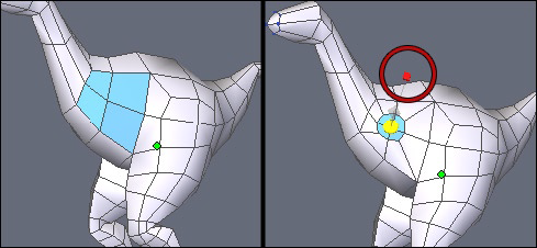
For the front legs, repeat more or less the same process as used for the rear legs. Start with an Inset using the Fast Extrusion (Ctrl), as shown on the surrounded part of the shot above.
Continue to do the extrusion sequence in order to model the arms. Do not hesitate to re-orient polygons before performing the next extrusion, since it is always performed perpendicularly to the selection.
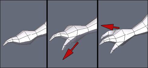
At the end, to model the wrist, do three extrusions corresponding to the claws. Nothing difficult here – the Fast Extrusion tool will do the job in few clicks!

The claws will be likely not sharp enough and not stretched enough.
The easiest solution to fix this small problem is to use the Soft Selection: Select a polygon (or a peak) at the end of the claws, then turn the Soft Selection on (F) in the Property Panel, and move the Manipulator. Keep in mind that you can use the Soft Selection option with the Tweak tool (Q).
Creating the Head's Details
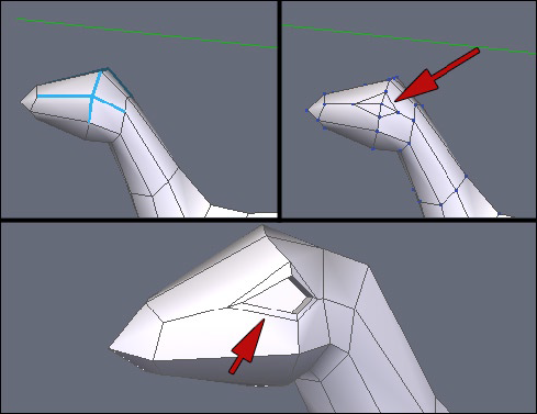
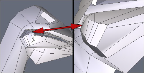
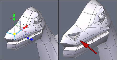
First step: the creation of the eye. A quick solution is to select the edges around a vertex, as shown in the top left shot, and to perform “Cut from Ring” operation (see above), which means to perform a Ring Selection, combined with a Connect (K then X).
Then, suppress the edges located inside the eye contour, as indicated by the red arrow above. Just select the edges, then use the Dissolve Tool (Backspace). Pay careful attention, in some cases, it may happen that a vertex still stays on your polygon. Do not forget to Dissolve it, as well.
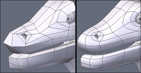
It is now time to shape the eye. Use Fast Extrusion again (Ctrl), with an Inset first (small red cube) and internal extrusion. You should get something similar to what shown in the bottom snapshot.
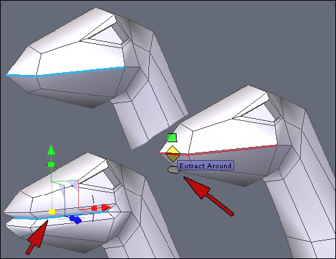
Let’s now start the Dinosaur’s maw. To do this, we are going to use “Edges Tools”.
Select the edges that define the boundary of the maw, as shown on the snapshot below. You can select an edge further to the rear, as it will be shown in the following snapshots.
Now, call the “Edge tools” (E): a small manipulator appears on the edges. Do a drag-and-drop on the blue manipulator (pointed by the red arrow on the snapshot), corresponding to the Extract Around operation, in order to specify the radius.
The selection must remain active. Now you just have to adjust the internal scale, by clicking on the small yellow cube of the Universal Manipulator. If needed, pull the selection a bit toward the inside.

Perform a small chamfer operation (Ctrl+F) or use the small green manipulator of the Edge Tool (E). Then, on the selection of the created polygons, do an Inset using the Fast Extrusion (Ctrl key on the red cube).
For practical issues, select the half of the model in Face Selection Mode (with display transparency turned on and in orthogonal view to make the selection easier). Then suppress – or mask – half of the polygons. This step will allow you to work in a more comfortable way inside the maw.
With the Tesselation Tool (X) and/or using the Edges Tools (E), tweak the shape of the mouth a bit. Be careful not to move the vertices located in the middle of the model, or only onto the vertical plane.
Repeat the above steps with the outside of the maw, to refine the jawbone shape. Edges Tools (E), combined with the Tesselation Tool (X), will once again facilitate this part of the work.
Be careful with your cuts. In some cases, you can create polygons with more than 4 sides (“n-gons”). Do not hesitate to work on them to get only quadrangles. Surrounded below, an edge has been added to divide the 6-edges polygon into two quadrangles. The operation was simple: the two opposite vertices were selected, then the Connect Tool (X) was been used to connect them.

Once the jawbone done, let’s work on the eye. The left shot shows edges which have been added, thanks to the Tesselation (X) and Edges Tools (E).
Take some time to Tweak (Q) the shape a bit more, in order to give a more natural aspect to it.
If you suppressed, as suggested before, the half of the model, take the Symmetry Tool, activate the Clone option, and create the mirror copy.
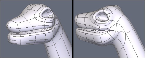
Finally, apply a smoothing (PageUp) to preview the result. If needed, use again the Tweak Tool (Q) to refine the shape of your model.
Once the contour of the eye is done, add a sphere in order to model the eyeball.
To model the nostril, use the same method as for the eye contour: a “Cut From Ring” (K then X) and several inset extrusions with the Fast Extrusion Tool (Ctrl).
Now use the Tweak Tool (Q) to refine the shape, and preview your final model by increasing the smoothing range (PageUp).
Details and Finish
The global model has now been created. Now is the time to add small details here and there.
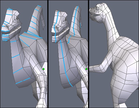
For example, add some slices to your model and use the Tweak Tool (Q) to refine the geometry more locally.
Above, a Ring (K), then Connect (X) have been applied on the whole length of the model. Keep in mind that you can use the second option of the Tesselation tool to achieve the same result. Please note however that the “Cut from Ring” operation is used more often, as it allows you to get a preview of the cut to be created, thanks to the prior Ring selection.

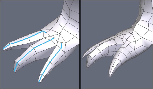
Work again then on the rear legs. Unlike the front legs, the claws have not been modeled yet. Same method here, e.g. Extrusion and Sweeping, starting from three polygons (indicated by the red arrows above).
If needed, tweak and refine the end of the leg to have the base polygons correctly located, using the Tesselation (X) or Edges Tools (E).
As mentioned previously, the orientation of the base polygons will drive the direction of further extrusions.
Add cuts to change the shape of the claws to your desired shapes.
Try as much as possible to keep 4-sided polygons. Also be careful to keep the mesh as uniform as possible, to avoid having dense areas of polygons and others with too low a density. This issue is important if you plan to use displacement brushes to model high-definition details afterwards.
Finally, if you wish to animate your model, do not forget to detail it around deformation areas, to have them performed in a fluid way.
Global Modifications
Before starting this step, if you previously masked the half of the model, be sure to unmask it. Then, select both parts of the model using the Shift key and use the Weld Tool, located in the Vertex Modeling tab.
If all boundary edges were strictly located on the symmetry plane, your model will be perfectly welded. If needed, manually weld vertices which have are disjoined.
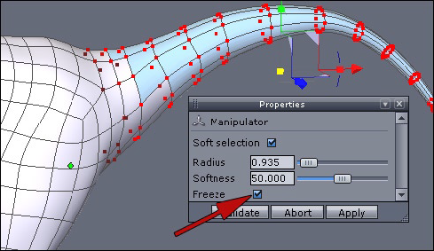
If you wish to modify a part of your model, such as changing the curvature of the tail, the easiest and fastest way is to use the Soft Selection.
A trick for the selection, provided by Emmanuel Rémia, is to select the polygon at the end of the tail and then, using the Ctrl / Command and “+” key combination (the “+” key of the numeric keypad) several times will expand the selection along the model topology, to reach the location which best suits your needs.
Then turn the Soft Selection on in the property panel, and check the Freeze option, which allows you to keep the attenuation influence of the selection even after you have moved it.
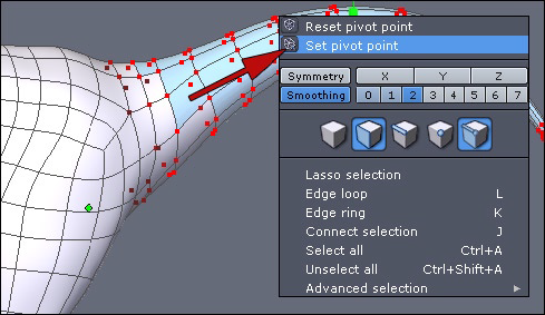
In the contextual menu, choose the “Set pivot point” utility, which will let you to place the Manipulator at a precise point on the model instead of the default location (which is the center of the selection).
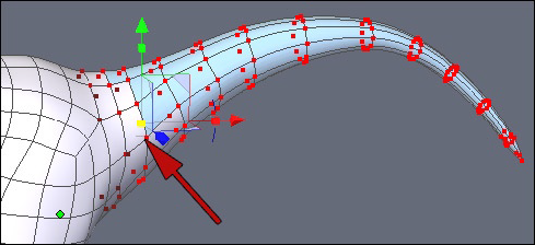
Click a vertex and perform rotations to change the aspect of the tail.
As you do these operations with different selections, do some of the operations with the Soft Selection mode activated and some without the mode activated to refine the shape of your model until you are satisfied.
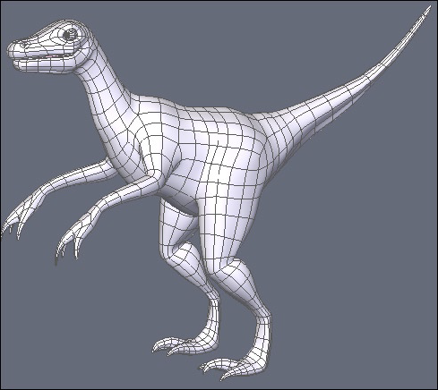
And voilà, the final dinosaur model! Of course, there are still small enhancements to do, additions, cuts, details to tweak, and your own personal touch.
We hope that through this example you have now a good overview of the Box Modeling technique.
It’s now up to you to get inspired from this example to realize even more advanced creations!
Page Tools
Except where otherwise noted, content on this wiki is licensed under the following license: CC Attribution 3.0 Unported
